


In this blog post we will learn about how we can create a donut/torus using <C> language.
Before making this blog I was reading another article written by Mr. Andy Sloane from which I came to know about the concept of this Donut Math. And my focus on this blog will be to make it a little beginner friendly. You can check out the original article written by Mr. Andy Sloane here.
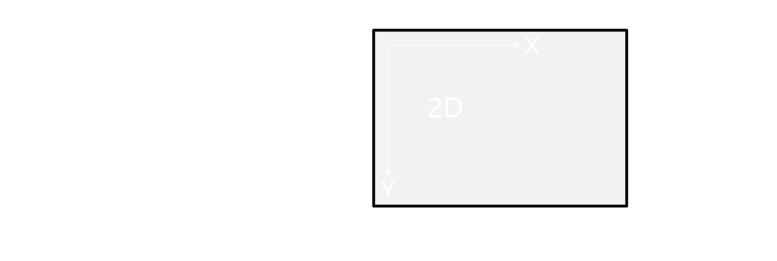
Now, let's have a look at the diagrams so that we can have a better understanding of what we need to do.
2D View :
Here, our goal is to make a 3D donut/torus which is rotating on two or more axis using different special characters for luminance.
3D View :
Before going straight to the coding part we need to know some mathematical concepts.
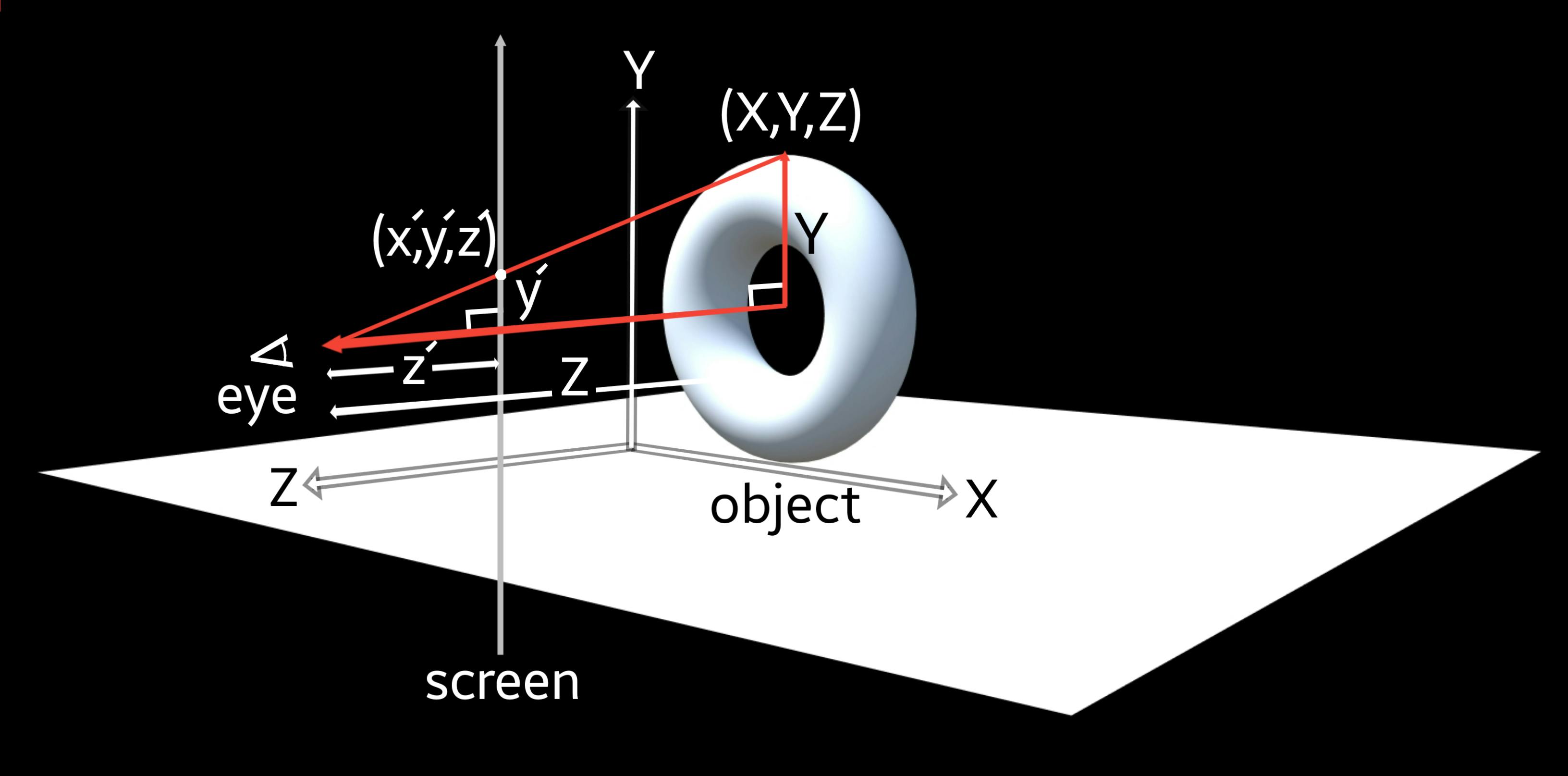
3D Projection:
A 3D projection (or graphical projection) is a design technique used to display a three-dimensional (3D) object on a two-dimensional (2D) surface. Wikipedia ArticleHere, as we are showing a 3D image on a 2D screen, so to do that we need to project the 3D co-ordinates in terms of 2D co-ordinates.
Now, to show the (X,Y,Z) in terms of 2D co-ordinates we will use (x',y',z'). Here, z' is nothing but the distance from the eye to the screen, so it'll be fair if we can assume it as a constant K. From the diagram we can see there are two similar right-angled triangles, so we can say,
 $$ (x', y') =
\left(
\frac{X K}{Z}, \frac{Y K}{Z}\\
\right) $$
Here, we can change the field of view by changing the value of K. Let's say the object which is in this case the donut/torus is 10 units wide and it is at the depth of 5 units from the viewer(follow the 3D diagram), that means X=10 and Z=5,
$$ (x', y') =
\left(
\frac{X K}{Z}, \frac{Y K}{Z}\\
\right) $$
Here, we can change the field of view by changing the value of K. Let's say the object which is in this case the donut/torus is 10 units wide and it is at the depth of 5 units from the viewer(follow the 3D diagram), that means X=10 and Z=5,
.'. (x', y') = (10 K/5, Y K/5)
Now, let's say the screen is 100x100px; and the torus will be shown at 50x50px
so, x' should be less than or equal to 50
=> x' <= 50
=> 10 K/5 <= 50
=> K <= 25
So, K which is equal to the distance from the viewer's eye to the screen is smaller than or equal to 25.
Now, to draw the donut/torus we need to know the concept of rotation matrix in 2D and 3D.
Rotation Matrix in 2D & 3D:
In linear algebra, a rotation matrix is a transformation matrix that is used to perform a rotation in Euclidean space. Wikipedia ArticleRotation Matrix in 2D:
Point A and B, both of which are at the 1 unit distance away from the origin in the X-Y plane rotate θ degree and become A' and B'.
In the diagram above the co-ordinates of point A is (1,0) and the co-ordinates of point B is (0,1). Now, representing the point A and B in matrix form,
$$ R\theta = \left( \begin{array}{cc} 1&0\\ 0&1 \end{array} \right) $$ After rotation, the new matrix form or to be exact the representation of A' and B' in matrix form will be, $$ R'\theta = \left( \begin{array}{cc} Cos\theta&-Sin\theta\\ Sin\theta&Cos\theta \end{array} \right) $$ Now, it's time to look into the rotational matrix in 3D.
Rotation Matrix in 3D:
To calculate rotational matrices in 3D, we will have three rotational matrices on three different axes.
1. Rotation About X-Axis:
Point A, B, and C are at 1 unit distance away from the origin where the points A and B rotates θ degree having the point C on the X axis fixed.
Here, the point on the X axis is C with the co-ordinates (1,0,0), point on Y axis is A with the co-ordinates (0,1,0) and point B is on the Z axis having the co-ordinates (0,0,1).
 Representing in matrix form,
$$ R\theta x = \left(
\begin{array}{ccc}
1&0&0\\
0&1&0\\
0&0&1
\end{array}
\right) $$
According to the above diagram, the point on X axis which is C has the co-ordinates (1,0,0), which is the same as before the rotation, as it is on a fixed axis. But the co-ordinates of the other two points A and B will change and become A' and B' after rotation with the co-ordinates (0, Cosθ, Sinθ) and (0, -Sinθ, Cosθ).
Representing in matrix form,
$$ R\theta x = \left(
\begin{array}{ccc}
1&0&0\\
0&1&0\\
0&0&1
\end{array}
\right) $$
According to the above diagram, the point on X axis which is C has the co-ordinates (1,0,0), which is the same as before the rotation, as it is on a fixed axis. But the co-ordinates of the other two points A and B will change and become A' and B' after rotation with the co-ordinates (0, Cosθ, Sinθ) and (0, -Sinθ, Cosθ).
Representing in matrix form after rotation, $$ R'\theta x = \left( \begin{array}{ccc} 1&0&0\\ 0&Cos\theta&-Sin\theta\\ 0&Sin\theta&Cos\theta \end{array} \right) $$ 2. Rotation About Y-Axis:
Point A, B, and C are at 1 unit distance away from the origin where the points A and B rotates θ degree having the point C on the Y axis fixed.
 Representing in matrix form,
$$ R\theta y = \left(
\begin{array}{ccc}
1&0&0\\
0&1&0\\
0&0&1
\end{array}
\right) $$
In the diagram above point C is on the fixed Y axis having the co-ordinates (0,1,0) after rotation. But the the co-ordinates of the points A(on Z axis) and B(on X axis) will change after rotation to (Cosθ, 0, -Sinθ) and (Sinθ, 0, Cosθ)
Representing in matrix form,
$$ R\theta y = \left(
\begin{array}{ccc}
1&0&0\\
0&1&0\\
0&0&1
\end{array}
\right) $$
In the diagram above point C is on the fixed Y axis having the co-ordinates (0,1,0) after rotation. But the the co-ordinates of the points A(on Z axis) and B(on X axis) will change after rotation to (Cosθ, 0, -Sinθ) and (Sinθ, 0, Cosθ)
Representing in matrix form after rotation, $$ R'\theta y = \left( \begin{array}{ccc} Cos\theta&0&Sin\theta\\ 0&1&0\\ -Sin\theta&0&Cos\theta \end{array} \right) $$ 3. Rotation About Z Axis:
Point A, B, and C are at 1 unit distance away from the origin where the points A and B rotates θ degree having the point C on the Z axis fixed.
 Representing in matrix form,
$$ R\theta z = \left(
\begin{array}{ccc}
1&0&0\\
0&1&0\\
0&0&1
\end{array}
\right) $$
In this case, the point C is on the fixed Z axis having the co-ordinates (0,0,1) after rotation. But the the co-ordinates of the points A(on X axis) and B(on Y axis) will change after rotation to (Cosθ, Sinθ, 0) and (-Sinθ, Cosθ, 0).
Representing in matrix form,
$$ R\theta z = \left(
\begin{array}{ccc}
1&0&0\\
0&1&0\\
0&0&1
\end{array}
\right) $$
In this case, the point C is on the fixed Z axis having the co-ordinates (0,0,1) after rotation. But the the co-ordinates of the points A(on X axis) and B(on Y axis) will change after rotation to (Cosθ, Sinθ, 0) and (-Sinθ, Cosθ, 0).
Representing in matrix form after rotation, $$ R'\theta z = \left( \begin{array}{ccc} Cos\theta&-Sin\theta&0\\ Sin\theta&Cos\theta&0\\ 0&0&1 \end{array} \right) $$
So far, we've discussed some of the key mathematical concepts. Now, it's time that we should talk about how we can draw the donut/torus.
Drawing the Torus:
A torus can be made by revolving a small circle (radius R²) along a line made by a bigger circle (radius R¹).

Now, to draw this torus we will have to rotate a point by ϕ degree, which will be on the circle with the radius R², and rotates that circle by θ degree.
In the diagram below we are rotating the point (R² Cosϕ, R² Sinϕ, 0) from 0 to ϕ degrees.
So, we can say
$$ (X, Y, Z) = \begin{array}{ccc} (R¹, 0, 0) + (R² Cosϕ, R² Sinϕ, 0)\\ \end{array} $$
$$ =>(X,Y,Z) = \begin{array}{ccc} (R¹+R² Cosϕ, R² Sinϕ, 0)\\ \end{array} $$
Now, we will rotate the circle of radius R² around the Y axis from 0 to θ degrees by multiplying a rotation matrix (about Y axis) with (X, Y, Z).
$$ (X, Y, Z) . \left( \begin{array}{ccc} Cosθ&0&Sinθ\\ 0&1&0\\ -Sinθ&0&Cosθ \end{array} \right) $$
$$ => (R¹+R² Cosϕ, R² Sinϕ, 0) .\left( \begin{array}{ccc} Cosθ&0&Sinθ\\ 0&1&0\\ -Sinθ&0&Cosθ \end{array} \right) $$
$$ => (X,Y,Z) = \left( \begin{array}{ccc} (R¹+R² Cosϕ)Cosθ, R² Sinϕ, (R¹+R² Cosϕ)Sinθ\\ \end{array} \right) $$
Up until now, we have successfully made the torus. Now, as we want our torus to rotate on at least two or more axis, so we will multiply two more rotation matrices with (X, Y, Z).
Let's say we want our torus to rotate in X and Z axis and to do that we'll use an angle A for X axis rotation and B for Z axis rotation.
The rotation matrix about X axis will be,
$$ R'Ax = \left( \begin{array}{ccc} 1&0&0\\ 0&CosA&-SinA\\ 0&SinA&CosA \end{array} \right) $$
The rotation matrix about Z axis will be,
$$ R'Bz = \left( \begin{array}{ccc} CosB&-SinB&0\\ SinB&CosB&0\\ 0&0&1 \end{array} \right) $$
So, the (X, Y, Z) will be,
$$ (X, Y, Z) .
\left(
\begin{array}{cc}
R'Ax\\
\end{array}\right).
\left(
\begin{array}{cc}
R'Bz\\
\end{array}\right) $$
$$ => (X, Y, Z) . \left( \begin{array}{ccc} 1&0&0\\ 0&CosA&-SinA\\ 0&SinA&CosA \end{array}\right) .\left(\begin{array}{ccc} CosB&-SinB&0\\ SinB&CosB&0\\ 0&0&1 \end{array} \right) $$
$$ =>((R¹+R² Cosϕ)Cosθ, R² Sinϕ, (R¹+R² Cosϕ)Sinθ). \left( \begin{array}{ccc} CosB&-SinB&0\\ CosASinB&CosACosB&-SinA\\ SinASinB&SinACosB&CosA \end{array}\right) $$
Now the final (X, Y, Z) will be,
$$ \left( \begin{array}{ccc} X\\ Y\\ Z \end{array}\right) = \left(\begin{array}{ccc} (R¹ + R² Cosϕ)(Cosθ CosB + Sinθ SinA SinB ) + (R² Sinϕ) (CosA SinB)\\ (R¹ + R² Cosϕ)(-SinB Cosθ + Sinθ SinA CosB) + (R² Sinϕ) (CosA CosB)\\ (R¹ + R² Cosϕ)(Sinθ CosA) + (R² Sinϕ) (-SinA) \end{array} \right) $$
After all this, now we have a co-ordinate or a point at the surface of the torus, which is rotating on two axes X and Z, which is centered at the origin.
As the viewer is at the origin so we won't be able to see the torus. So, to make it visible we'll have to add another constant K' with the Z to move the torus in front of the viewer.
So, our new 3D projection co-ordinates will be,
$$ (x', y') = \left( \frac{X K}{K'+Z}, \frac{Y K}{K'+Z}\\ \right) $$
We can easily change the depth of view and the field of view with the help of K and K' constants.
After making the torus and setting up the depth of view and the field of view, now it's time to work on illumination. Here, depending on the illuminance we will put different special characters (to be exact 12 which are ".,-~:;=!*#$@") to represent different shades from darkest to brightest. We can measure the illuminance by calculating the dot product of the surface normal and lighting direction.

Let's say if the dot product is greater than 1 that means that pixel should contain a character with a bigger surface area (like "@") and if it is lower then it will contain a character with lower surface area (like ".").
Surface Normal:
In geometry, a surface normal or simply normal is an object such as a line, ray, or vector that is perpendicular to a given object. Wikipedia Article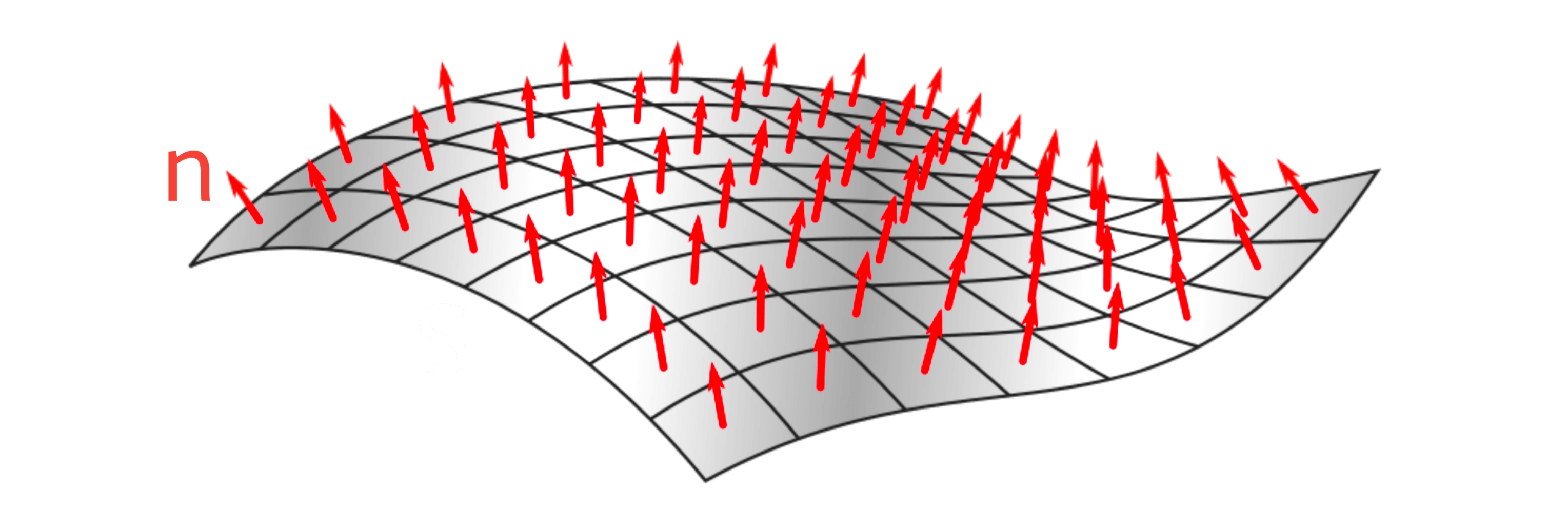 Surface normal is shown in the above diagram (n). Here, the vector n is perpendicular to the surface S. So, n can be called as normal vector of the surface S.
Surface Normal of the Torus:
For our torus, we took a point on a circle (radius R²) and rotated it around the central axis of the torus and rotated that torus on two more axes as well. Here, the surface normal will be similar to (X, Y, Z) but the only difference is the surface normal will be a point on the unit circle centered on the origin.
So, instead of (R¹+R² Cosϕ, R² Sinϕ, 0), we will start with (Cosϕ, Sinϕ, 0) and then multiply all the other rotation matrices with it.
The surface normal will be,
$$ (Nx, Ny, Nz) = (Cosϕ, Sinϕ, 0) . \left( \begin{array}{ccc} Cosθ&0&Sinθ\\ 0&1&0\\ -Sinθ&0&Cosθ \end{array} \right) . \left( \begin{array}{ccc} 1&0&0\\ 0&CosA&-SinA\\ 0&SinA&CosA \end{array} \right) .\left( \begin{array}{ccc} CosB&-SinB&0\\ SinB&CosB&0\\ 0&0&1 \end{array} \right) $$
$$ \left( \begin{array}{ccc} Nx\\ Ny\\ Nz \end{array}\right) = \left(\begin{array}{ccc} (Cosϕ)(Cosθ CosB+Sinθ SinA SinB)+(Sinϕ)(CosA SinB)\\ (Cosϕ)(-SinB Cosθ+Sinθ SinA CosB)+(Sinϕ)(CosA CosB)\\ (Cosϕ)(Sinθ CosA)+(Sinϕ)(-SinA) \end{array} \right) $$
Now, that we've calculated the surface normal, it's time for the lighting.
Lighting the Torus:
At first, we must choose where to put the light source. Let's put the light above the torus slightly facing it's behind. Which means, the light will be on (0,1,-1).
Note: The light vector should be a normalized vector, which means the length of the light vector should be 1. Stackoverflow Article
But in this case, the magnitude will be,
$$ \sqrt{(0)²+(1)²+(-1)²} = \sqrt{2} $$
Finally, the result of illuminance will be,
$$ L = (Nx, Ny, Nz) . (0,1,-1) $$
$$ => L = \left(-Cosϕ SinB cosθ + Cosϕ Sinθ SinA CosB + Sinϕ CosA CosB - Cosϕ Sinθ CosA + Sinϕ SinA \right) $$
Here, one thing to note is the value of illuminance will be from -√2 to √2.
Okay now, it's time to move on to the coding part.
Steps to create the torus:
Headers Used:
//Donut Math
#include <stdio.h>
#include <string.h>
#include <stdlib.h>
#include <conio.h>
#include <math.h>
Variables Used:
//Screen Resolution Variables
const int screen_width = 85;
const int screen_height = 22;
//Buffer variables
int buffer_size = 1870;
float z_buffer[buffer_size];
char output_buffer[buffer_size];
//X and Z axis rotation angles
float A = 0, B = 0;
//Torus making angles
float theta, phi;
//Spacing Variables
const float theta_step = 0.02;
const float phi_step = 0.02;
//Circle radius and constant
const float R¹ = 3;
const float R² = 1.8;
const float K¹ = 10;
//X = R¹+ R²;
//We want our torus to be displaced 1/8th of the width of the screen,
//which is 1/4th of the way from the center to the side of the screen.
const int K = (screen_width * K¹ * 1) / (8 * (R¹ + R²));
Code Explanation:
We've selected all the values for different variables for our torus.
Here, as we know
$$ x' = \left( \frac{X K}{K'+Z}\\ \right) $$
we can say, $$ => \frac{screen width}{5} = \frac{X K}{K'+0}\\ $$
$$ => \frac{screen width * K'}{5} = {X K}\\ $$
$$ => \frac{screen width * K'}{5} = {(R¹ + R²) K}\\ $$
$$ => K = \frac{screen width * K'}{5 (R¹ + R²)}\\ $$
Build-in Functions Used:
- system()
- gotoxy()
- sin() & cos()
- memset()
- putchar()
system() & gotoxy()
The system() function is a part of the C/C++ standard library. It is used to pass the commands that can be executed in the command processor or the terminal of the operating system, and finally returns the command after it has been completed.<stdlib.h> or <cstdlib> should be included to call this function.Here, we've used
system("cls"), which clears the screen or console window of commands and any output generated by them.
The gotoxy() function places the cursor at the desired location on the screen. This means it is possible to change the cursor location on the screen using the gotoxy() function. It is used to print text wherever the cursor is moved. To use this function, we need to include <conio.h> header.
//C programme to demonstrate the system() and gotoxy() function
#include <stdio.h>
#include <stdlib.h>
#include <conio.h>
#include <time.h>
int main(int argc, char *argv[])
{
    printf("Let's build a 3D Torus!");
    //putting the cursor at the beginning
    gotoxy(0,0);
    sleep(2);
    printf("Let's build a 3D Donut!");
    gotoxy(0,0);
    sleep(2);
    //Clearing the screen
    system("cls");
}
Code Output:

sin() & cos()
The C library function can be declared as double sin(double x) and double cos(double x) using the parameter x, which is a floating point value representing an angle expressed in radians. The sin() and cos() functions can be used to return the sine and cosine of a radian angle x.//C programme to show how to implement the sin() amd cos() function
#include <stdio.h>
#include <math.h>
#define PI 3.14159265
int main(int argc, char *argv[])
{
double x,val,result;
printf("Please put a value for x = ");
scanf("%lf",&x);
val = PI/180;
result = sin(x*val);
printf("The sine of %lf is %lf",x,result);
}
Code Output:

memset()
The C library function memset() is used to fill a block of memory with a particular value.The memset() function can be declared as
void *memset(void *ptr, int x, size_t count)
Where,
ptr = Starting address of memory to be filled,
x = Value to be filled,
count = the number of bytes to be filled starting from ptr.
//C programme to implement the memset() function
#include <stdio.h>
#include <string.h>

int main()
{
    char str[32] = "Let's make a 3D rotating Torus!";
    printf("Before using memset() function = %s\n", str);
    memset(str + 16, '*', 8 * sizeof(char));
    printf("After using memset() function = %s", str);
    return 0;
}
Code Output:

putchar()
putchar(int char) is a C standard library function that prints a single character on the output screen. It can be parameterized using a char which is the character to be written to stdout.//This progrmamme will show the implementation of putchar() function
#include <stdio.h>
int main()
{
char ch[23] = "We are making a torus!";
for (int i = 0; i <= 21; i++)
{
putchar(ch[i]);
}
return 0;
}
Code Output:

Custom Functions Used:
- render_frame()
- display()
render_frame()
This function will process each pixel depth information(here, Zi tells us how far the pixel of the torus will be from the viewer) and the illuminance_lvl of the torus after which it'll store that depth information in z_buffer followed by the suitable special character (depending on the illuminance_lvl) in output_buffer.void render_frame(const int screen_width, const int screen_height, int buffer_size, float z_buffer[buffer_size], char output_buffer[buffer_size], float A, float B)
{
//Torus making angles
float theta, phi;
//Spacing Variables
const float theta_step = 0.02;
const float phi_step = 0.02;
//Circle radius and constant
const float R¹ = 3;
const float R² = 1.8;
const float K¹ = 10;
const double two_pi = 6.2831;
//X = R¹+ R²;
//We want our torus to be displaced 1/8th of the width of the screen,
//which is 1/4th of the way from the center to the side of the screen.
const int K = (screen_width * K¹ * 1) / (8 * (R¹ + R²));
memset(output_buffer, ' ', buffer_size);
memset(z_buffer, 0, buffer_size * sizeof(float));
for (theta = 0; theta <= two_pi; theta += theta_step)
{
for (phi = 0; phi <= two_pi; phi += phi_step)
{
float sin_phi = sin(phi),
cos_phi = cos(phi),
sin_theta = sin(theta),
cos_theta = cos(theta),
sinA = sin(A),
cosA = cos(A),
sinB = sin(B),
cosB = cos(B),
circlex = R¹ + (R² * cos_phi),
circley = (R² * sin_phi);
//3D co-ordinate after rotation
float X = (circlex * cos_theta * cosB + circlex * sin_theta * sinA * sinB + circley * sinB * cosA);
float Y = (-circlex * sinB * cos_theta + circlex * sin_theta * sinA * cosB + circley * cosA * cosB);
float Z = (circlex * sin_theta * cosA - circley * sinA);
//pixel depth info
float Zi = 1 / (Z + K¹);
//Xp and Yp or 3D projection co-ordinates
int Xp = screen_width / 2 + X * 2 * K * Zi;
int Yp = (screen_height / 2 + 1) - Y * K * Zi;
int i = Xp + screen_width * Yp;
//Calculating illuminance, in the range of 12 different levels (from 0 to 11) (8*sqrt(2) = 11.3)
float L = (-cos_phi * sinB * cos_theta + cos_phi * sin_theta * sinA * cosB + sin_phi * cosA * cosB - cos_phi * sin_theta * cosA + sin_phi * sinA);
int illuminance_lvl = L * 8;
if (Xp > 0 && Xp < screen_width && Yp > 0 && Yp < screen_height && Zi > z_buffer[i])
{
z_buffer[i] = Zi;
output_buffer[i] = ".,-~:;=!*#$@"[illuminance_lvl > 0 ? illuminance_lvl : 0];
}
}
}
}
Code Explanation:
In this function after declaring all the required variables and constants, we will use memset() function to put a blank space in every pixel buffer location in output_buffer. Later on, when we will plot all the pixels in each frame according to the illuminance level and the 3D projection co-odinates, these blank spaces together will crate the background.
memset(output_buffer, ' ', buffer_size);
Now, you may have a question like, how are we converting the 3D projection co-ordinates(Xp and Yp) to pixel buffer location(output_buffer[i], here i is the buffer location)?
It is really simple the formula is i = Xp + screen_width x Yp. Now, another question, why should we do this? the benefit of this approach, we will see in the display() function.
After this, we'll do the same with z_buffer but this time instead of putting blank spaces(as z_buffer is only for storing floating point nums), we'll simply put 0.
memset(z_buffer, 0, buffer_size * sizeof(float));
Moving on to the next step, we will compute all the 3D co-ordinates, 3D projection co-ordinates and illuminance. But before that we will have to calculate the sine of theta/phi, cosine of theta/phi, sine of A/B, cosine of A/B not to forget circlex and circley. So to do that we need a nested for loop(one for theta and one for phi). Here, these for loops will be initialised from 0 to 2xPI = 6.2831.
Now, let's talk about 3D projection co-ordinates. So, earlier on, we've already calculated the 3D projection co-ordinates which are Xp = X * K * Zi and Yp = Y * K * Zi.
Now, if we use int Xp = X * K * Zi and int Yp =Y * K * Zi in our code, we'll see an output something like this,
Output:

As it seems we have a problem. We need to move the torus in the center of the screen. So that's why we'll add screen_width / 2 with Xp and screen_height / 2 with Yp
Output:
Notice that the shape of the torus is not a circle it's more of like an oval. So, to fix that we'll multiply 2 with the value of X to increase the width of the torus.
Now, the code will be like this,
//Xp and Yp projection or 3D projection co-ordinates
int Xp = screen_width / 2 + X * 2 * K * Zi;
int Yp = screen_height / 2 - Y * K * Zi;
You can always tweak the code a bit to get the best output.
Note: Here, for Yp notice that Y is negative. It is because in 3D space, Y moves in an upward direction but in 2D screen Y will move in the downward direction.
Finally, after calculating all of this now, to store the depth info on z_buffer and the special character (according to the illuminance_lvl) in output_buffer, we need to put an if condition to check,
1. Xp > 0 && Xp < screen_width
2. Yp > 0 && Yp < screen_height
3. Zi > z_buffer[i]
The first two conditions are pretty straightforward forward but talking about the third condition, we are making sure that every pixel buffer location of z_buffer should contain the greatest depth value possible, which means that the pixel which is closest to the viewer(depth wise) that will only be allowed to plot to the screen.
display()
Using this function will print out those special characters on the output screen with the help of putchar() function and output_buffer.void display(int buffer_size, const int screen_width, char output_buffer[buffer_size])
{
//Putting the cursor to the home position
gotoxy(0, 0);
for (int k = 0; k <= buffer_size; k++)
{
putchar(k % screen_width ? output_buffer[k] : '\n');
}
}
Code Explanation:
At first we will put the cursor at the home position using gotoxy() function. After this, as we've already stored all the special chars in consecutive order in output_buffer(this was the benefit that I was talking about earlier), now we just need a for loop to print it out.
The for loop will be initialised from k = 0 upto k <= buffer_size.
Now, let's talk about the expression,
putchar(k % screen_width ? output_buffer[k] : '\n');
With this putchar function, we are printing one pixel at a time using a conditional operator.
If, k % screen_width ≠ 0 then true and that particular pixel will be printed, and if k % screen_width = 0 then false, which means we are at the end of the line and that's why we'll print a '\n' = newline.
Output:

Final Code:
//Donut Math
#include <stdio.h>
#include <string.h>
#include <stdlib.h>
#include <conio.h>
#include <math.h>
void render_frame(const int screen_width, const int screen_height, int buffer_size, float z_buffer[buffer_size], char output_buffer[buffer_size], float A, float B)
{
    //Torus making angles
    float theta, phi;
    //Spacing Variables
    const float theta_step = 0.02;
    const float phi_step = 0.02;
    //Circle radius and constant
    const float R¹ = 3;
    const float R² = 1.8;
    const float K¹ = 10;
    const double two_pi = 6.2831;
    //X = R¹+ R²;
    //We want our torus to be displaced 1/8th of the width of the screen,
    //which is 1/4th of the way from the center to the side of the screen.
    const int K = (screen_width * K¹ * 1) / (8 * (R¹ + R²));

    memset(output_buffer, ' ', buffer_size);
    memset(z_buffer, 0, buffer_size * sizeof(float));

    for (theta = 0; theta <= two_pi; theta += theta_step)
    {
        for (phi = 0; phi <= two_pi; phi += phi_step)
        {
            float sin_phi = sin(phi),
                  cos_phi = cos(phi),
                  sin_theta = sin(theta),
                  cos_theta = cos(theta),
                  sinA = sin(A),
                  cosA = cos(A),
                  sinB = sin(B),
                  cosB = cos(B),
                  circlex = R¹ + (R² * cos_phi),
                  circley = (R² * sin_phi);
            //3D co-ordinate after rotation
            float X = (circlex * cos_theta * cosB + circlex * sin_theta * sinA * sinB + circley * sinB * cosA);
            float Y = (-circlex * sinB * cos_theta + circlex * sin_theta * sinA * cosB + circley * cosA * cosB);
            float Z = (circlex * sin_theta * cosA - circley * sinA);
            //pixel depth info
            float Zi = 1 / (Z + K¹);
            //Xp and Yp or 3D projection co-ordinates
            int Xp = screen_width / 2 + X * 2 * K * Zi;
            int Yp = (screen_height / 2 + 1) - Y * K * Zi;
            int i = Xp + screen_width * Yp;

            //Calculating illuminance, in the range of 12 different levels (from 0 to 11) (8*sqrt(2) = 11.3)
            float L = (-cos_phi * sinB * cos_theta + cos_phi * sin_theta * sinA * cosB + sin_phi * cosA * cosB - cos_phi * sin_theta * cosA + sin_phi * sinA);
            int illuminance_lvl = L * 8;

            if (Xp > 0 && Xp < screen_width && Yp > 0 && Yp < screen_height && Zi > z_buffer[i])
            {
                z_buffer[i] = Zi;
                output_buffer[i] = ".,-~:;=!*#$@"[illuminance_lvl > 0 ? illuminance_lvl : 0];
            }
        }
    }
}
void display(int buffer_size, const int screen_width, char output_buffer[buffer_size])
{
//Putting the cursor to the home position
gotoxy(0, 0);
for (int k = 0; k <= buffer_size + 1; k++)
{
putchar(k % screen_width ? output_buffer[k] : '\n');
}
}
int main()
{
//Screen Resolution Variables
const int screen_width = 85;
const int screen_height = 22;
//Buffer variables
int buffer_size = 1870;
float z_buffer[buffer_size];
char output_buffer[buffer_size];
//X and Z axis rotation angles
float A = 0, B = 0;
//Putting the cursor to home position
gotoxy(0, 0);
//Clearing the screen
system("cls");
for (;;)
{
//Function Calling
//Generating the frame
render_frame(screen_width, screen_height, buffer_size, z_buffer, output_buffer, A, B);
//Displaying the frame
display(buffer_size, screen_width, output_buffer);
//Spacing Variables for X and Z axis rotation
A += 0.03;
B += 0.03;
}
}
If you're on windows this may not work as expected. So, you can try this code instead, GitHub Repo: github.com/Shreyosgit/3D-Donut-Math
Code Output:
